Carrier Board

Max Gallup
Founding Member, Ex-Hardware Lead and Ex-Project Administrator
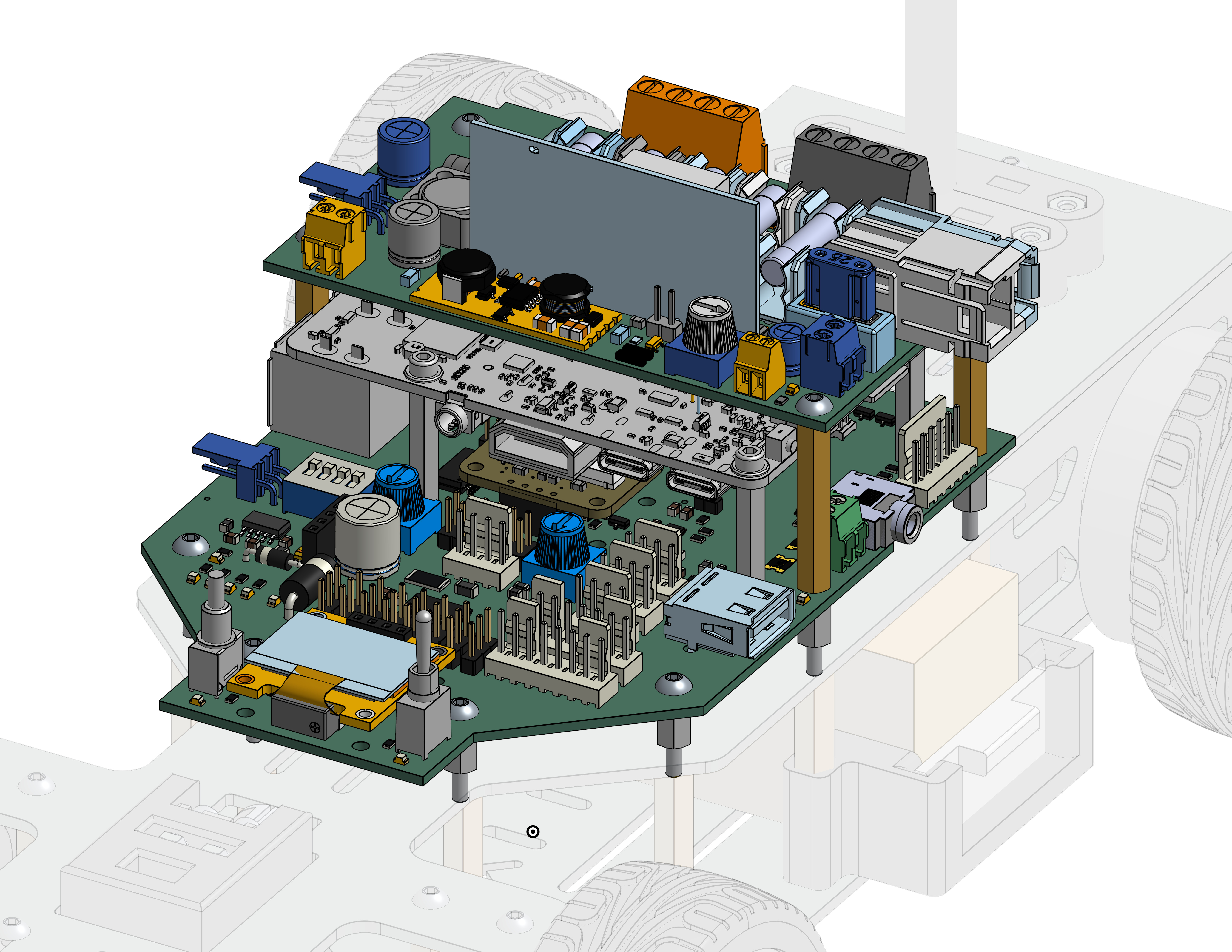
In order to use the Debix to its fullest extent, we provide the carrier board which the Debix connects to. As we can see in the picture below, the Debix (grayed-out) is sandwiched in-between two PCBs (printed circuit boards). Let's take a look at what each of them do:
-
Power Distribution Board - the smaller board above the Debix is directly connected to the battery and ensures we have a clean and regulated supply of power to the rest of the system. It powers the motors directly and feeds 5V to the the entire carrier board below.
-
Carrier Board - If the Debix is the brain of the Rover, then the Carrier Board is the spinal cord. The carrier board extends the pins of the Debix conveniently allowing us to plug in multiple sensors at once. It also has some more features that will be described on this page with greater detail.
The most basic function of the Carrier board is to connect the signal wires that go to the motors and servo to the Debix. To understand this better, we need to understand the type of signals that the motors and servo require. Both of them are controlled via PWM which basically communicates to the receiver a value between nothing and full. The TLDR is that it rapidly sets the signal high and low and the receiver measures the time low vs the time high computes the resulting ratio. Then, the servo for example, will interpret a signal of fully off as steering all the way left and fully on signal as all the way right. This allows for fine steering control of the servo.
However, the Debix does not have a PWM output pin, so we require a device in the middle known as the PCA-9865. It is a small IC (integrated circuit) that controls up to 16 PWM channels via commands over an I2C connection, which the Debix does have (in fact, it has 2 separate I2C devices). We integrated this little IC into the carried board. You can find it right behind where the wires from the servo and motors connect to the carrier board.
The following is an incomplete but simplified block diagram of the Carrier Board:

Firstly, we see that I2C connections (in blue) go from the Debix directly to the PCA-9685. The reason we put the motors and servo on their own I2C device was for robustness. Any other sensor that might crash the bus should not prevent the rover from sending commands to the motors and servo. Secondly, the PCA sends signals (in green) to the motors and servo. Other components such as the display, the ultrasonic sensor, or any device that communicates over I2C can be connected to I2C-device 5 via the exposed (white) connectors.
Download the Schematics
The carrier board exposes much more functionality than mentioned above. For a complete understanding of various components and interconnections, please download the schematics:
Acknowledgements: the Power Delivery Board (PDB) and Printed Circuit Board (PCB) were both designed by Niels Althuisius, with indispensable support from the VU Beta electronics and hardware labs.
Wiring Connections
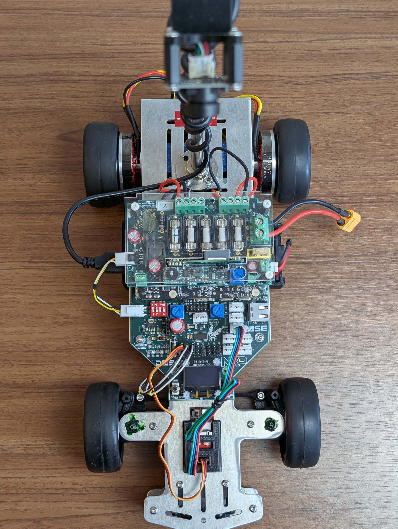
Here is a reference image of all default connections of the entire Rover.
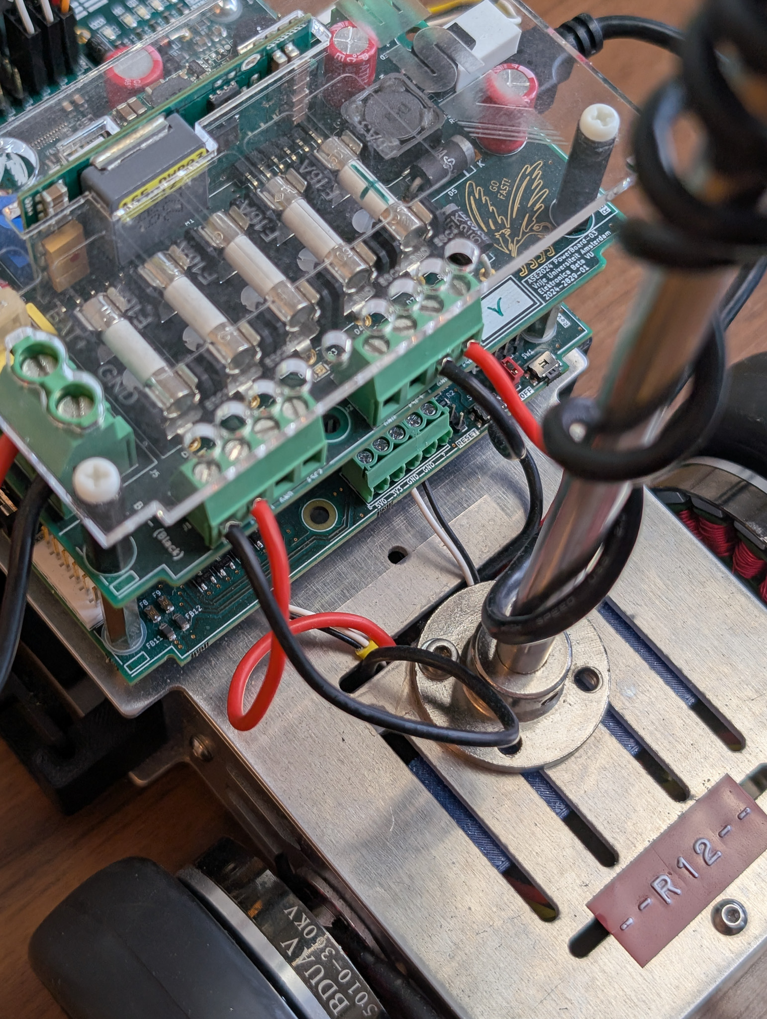
The motors get power directly from the power-distribution-board, seen here from the back.
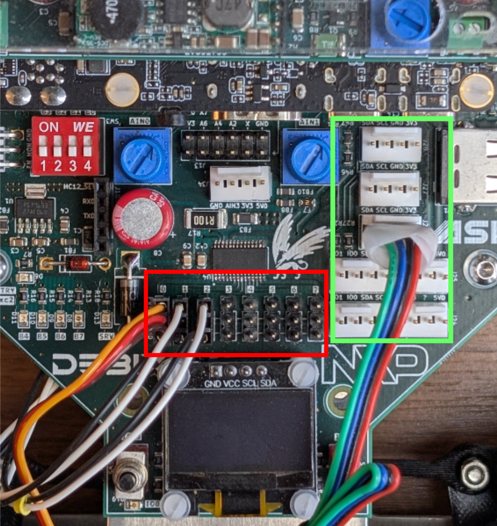
In the picture below, the red box highlights the 16 PWM outputs from the PCA-9865. The following channels are used: 0. Servo
- Left Motor
- Right Motor
The I2C bus connections are highlighted in green, currently only occupied by the ultrasonic sensor. Note, this is a shared bus meaning that any other I2C devices can be plugged in.